Valid For
- Volvo Chassis – All-new Volvo VNL
- Mack Chassis – Mack Pioneer, All-new Mack Anthem
This solution outlines the proper procedures and precautions for safely jump charging trucks with 12V and 24V systems, detailing the correct methods to avoid damage and ensure efficient battery charging for both Dual Energy Storage System (DESS) and Single Energy Storage System (SESS) variants.
When charging the truck, either a 12V charger or 24V charger may be used, so long as the correct method is used. Incorrect use of the charger will severely damage the system. Only use the charging methods outlined in this document.
Definitions
- BPMU: Battery Power Management Unit
- DESS: Dual Energy Storage System (variant ESO-BC) – Includes UC/ESM
- Uncontrolled Copy
- ECI: External Charging Interface
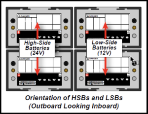
- HSB: High-Side (24V) Battery
- LSB: Low-Side (12V) Battery
- MDS: Maintenance Disconnect Switch
- SESS: Single Energy Storage System (variant ESO-B) – Without UC/ESM
- UC/ESM: Ultra Capacitor/Engine Start Module
Precautions
- To avoid the risk of arcing/electrocution, DO NOT connect the charger directly to the UC/ESM.
- The ECI can be identified by the red cap which states 12V. ONLY 12V CHARGERS MAY BE CONNECTED TO THE ECI.
- Ensure there are no loose connections between the charging source and the ECI studs.
- Replace the ECI top cover once the charging process is complete. This protects the ECI studs from dust and water.
Important Note: In the event of an extremely low state of charge, a charger in Smart Charge mode may not be able to charge the batteries. In this case, use a charger with Power Supply mode activated to charge the batteries up to a normal level.
12V Charging
High-Side Batteries are Measuring at 10V or Higher
Note: The BPMU requires a minimum of 10V in order to supply power and provide battery equalization. Refer to the section below if the HSBs are measuring below 10v.
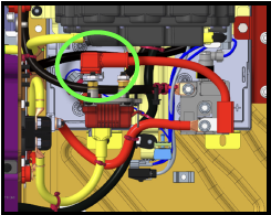
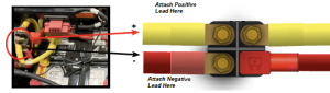
- Remove the red cover of the ECI (pictured lower-right)
- Connect battery charger positive (+)lead to ECI positive (+) stud (leftmost stud).
- Connect battery charger negative (-)lead to ECI negative (-) stud (rightmost stud).
- Turn on the charger.
- Check the battery voltage on the instrument cluster display. Start the truck once the following voltage conditions are met:
- DESS: The UC/ESM will be ready to crank at 16V – 17V
- SESS: The truck will require at least 20V to crank
- The truck must remain running or connected to the charger until the state of charge meter is at least 85%full (pictured below).
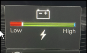
- Once the state of charge reaches 85% or higher, the truck may be turned off or the charger removed. Ensure that the red ECI cap is replaced. The charging process is now complete.
12V Charging
High-Side Batteries are Measuring at Less Than 10V
Note: The BPMU requires a minimum of 10V in order to supply power and provide battery equalization. Refer to the section above if the HSBs are measuring at 10V or more.
- Follow the procedure outlined in Section above to charge the LSBs.
- Once the LSBs are completely charged, remove the positive and negative leads of the charger from the ECI.
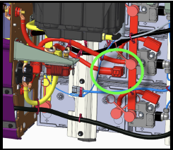
- Connect the positive lead of the charger to the upper-outboard terminal located on cable routed from the high-side battery bank
- Connect the negative lead of the charger to the bottom-outboard terminal located cable.

- Allow the HSBs to fully charge. DESS: The UC/ESM should be fully charged and ready to crank within 1-5 minutes SESS: A minimum time of 30-60 minutes will be required to charge the batteries
- Check the battery voltage on the instrument cluster display. Start the truck once the following voltage conditions are met: DESS: The UC/ESM will be ready to crank at 16V – 17V SESS: The truck will require at least 20V to crank
- The truck must remain running or connected to the charger until the state of charge meter is at least 85% full (pictured below).
- Once the state of charge reaches 85% or higher, the truck may be turned off or the charger removed. Ensure that the red ECI cap is replaced. The charging process is now complete.
24V Charging
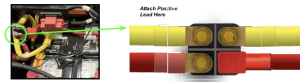
Note: Only the negative ECI terminal is used for 24V charging. DO NOT connect the positive lead of the charger to the positive post of the ECI.
- Connect the positive lead of the charger to the upper-outboard terminal located on (24V) cable routed from the high-side battery bank.

- Connect the ground lead of the charger to the negative terminal on the ECI port.

- Allow the high-side batteries to fully charge
- DESS: The Ultra Capacitor should be fully charged and ready to crank within 1-5 minutes.
- SESS: A minimum time of 30-60 minutes will be required to charge the batteries.
- Check the battery voltage on the instrument cluster display. Start the truck once the following voltage conditions are met.
- DESS: The UC will be ready to crank at 16V – 17V
- SESS: The truck will require at least 20V to crank
- The truck must remain running or connected to the charger until the state of charge meter is at least 85% full (pictured below).

- Once the state of charge reaches 85% or higher, the truck may be turned off or the charger removed. Ensure that the red ECI cap is replaced. The charging process is now complete.
Shore Power Charging
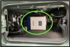
Note: This section is only applicable to 6-battery DESS trucks equipped with an inverter.
- Open the storage compartment on the passenger side of the truck to verify that the truck is equipped with an inverter (pictured below).

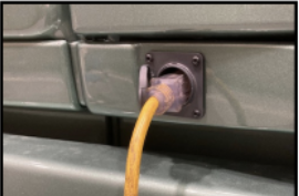
- Plug an HD power cord routed from the charging source into the shore power connector, located on the passenger side of the truck. The batteries will automatically begin to charge.

- Allow the batteries to fully charge.
- Note: The UC/ESM should be fully charged and ready to crank within 1-5 minutes.
- Check the battery voltage on the instrument cluster display. The UC/ESM will be ready to crank at 16V – 17V. Start the truck once this voltage condition is met.
- The truck must remain running or connected to the charger until the state of charge meter is at least 85% full (pictured below).
- Once the state of charge reaches 85% or higher, the truck may be turned off or the charger removed. Ensure that the red ECI cap is replaced. The charging process is now complete.
Charging With Another Truck
Legacy Truck (12V)
To charge the truck with a 12V Legacy truck, refer to Section 4.0 – 12V Charging. Jumper cable leads should be attached to the positions noted in Section 4.0.
All-new Truck (24V)
To charge the truck with a 24V Mack or Volvo truck, refer to Section 5.0 – 24V Charging. Jumper cable leads should be attached to the positions noted in Section 5.0.
Charging Failure
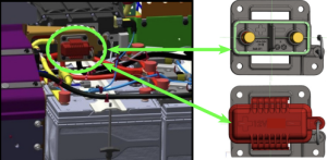
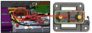
- Should the system fail to charge via the ECI, refer to the diagnostic procedures for checking the ECI fuse.
- For 4 and 6 battery options, the 500A Z-Case fuse is mounted on the battery end of the positive ECI cable (pictured below).

- For the 2 battery option, the 500A Z-Case fuse is mounted on the ECI end of the positive ECI cable (pictured below).